← notes / 2026.10.15
build log: iot smoke and gas sensor network
no repo yet. there isn’t enough code to deserve one.
the idea is a network of small wireless nodes that sense smoke, combustible and toxic gas, temperature, and humidity, and raise an alert two independent ways. one path is wifi to a live dashboard. the other is a lora radio mesh that needs no wifi, no cell service, and no building power.
why build it
commercial fire alarm systems are networks of sensors reporting back to a control panel. most fpe students only know how to pick those systems out of a catalog. building one from individual sensors up means actually dealing with how detection works at the physical layer: what the sensor signal looks like, whether its voltage is safe for the thing reading it, where to set a threshold, and how the alert gets anywhere.
the mesh is the part with an actual fpe argument behind it. a notification path that dies with the building’s wifi or power isn’t much of a notification path, so the second route has to survive losing both.
how a node works
each node is a heltec wifi lora 32 v4, an esp32-s3 with a lora radio and a tiny oled built in. every loop it reads its sensors, compares them against thresholds, sends readings to the dashboard over wifi, and if something crosses a threshold, broadcasts a lora alert over a meshtastic mesh. meshtastic is open source firmware where every node relays packets for the others, so an alert can hop its way across nodes that can’t reach each other directly.
the sensors are an mq-2 for smoke and combustible gas, an mq-135 for air quality, and a dht22 for temperature and humidity.
the voltage divider isn’t optional
the mq sensors run on 5v, and their analog output climbs toward 5v as gas concentration rises. the esp32’s analog pins tolerate 3.3v at most. 5v on one of those pins can permanently damage it, and this is the number one way these builds die.
so every mq signal goes through a voltage divider first, two resistors in series with the output taken from the middle.
v_out = v_in × r_bottom / (r_top + r_bottom)
      = 5 × 150k / (100k + 150k)
      = 3.0v
i aimed for 3.0v instead of exactly 3.3v on purpose, to leave margin for sensor overshoot and resistor tolerance. the original plan used 170k and 330k to land on 3.3v exactly, which had no margin, and 170k isn’t in normal resistor kits anyway. the rule going forward is to measure the divider output with a multimeter before it ever touches the board.
the pin trap
the esp32 has two analog-to-digital converters, adc1 and adc2, and adc2 stops working whenever wifi is on. a sensor wired to an adc2 pin works perfectly in testing and then quietly reads nothing once wifi gets added. the reference project i’m borrowing the sensing layer from uses one of those pins, which is only fine because it never turns wifi on. this one has to use adc1. on top of that, the “gpio 32 to 39” rule everyone quotes is for the original esp32, not the s3, so the actual pins get checked against the v4 pinout before anything gets wired.
scope
three nodes. one node is just a sensor, two is a point to point link, and three is the minimum that proves the mesh, by putting nodes 1 and 3 out of range of each other and showing node 2 relaying between them.
i’m buying one node first and fully validating it before spending money on the other two. the sensor multipacks already cover most of all three.
it’s done when:
- all three nodes read every sensor reliably
- a live dashboard shows all three
- thresholds are tuned so a real smoke source trips cleanly without constant false alarms
- a lora alert propagates with wifi turned off
- a node relays a message it couldn’t have delivered directly
threshold tuning is the part i’m most interested in. too sensitive and burnt toast sets it off, too loose and it misses a real event. that judgment is basically the job, so how the thresholds get chosen and tested is going to be documented properly.
where it actually is
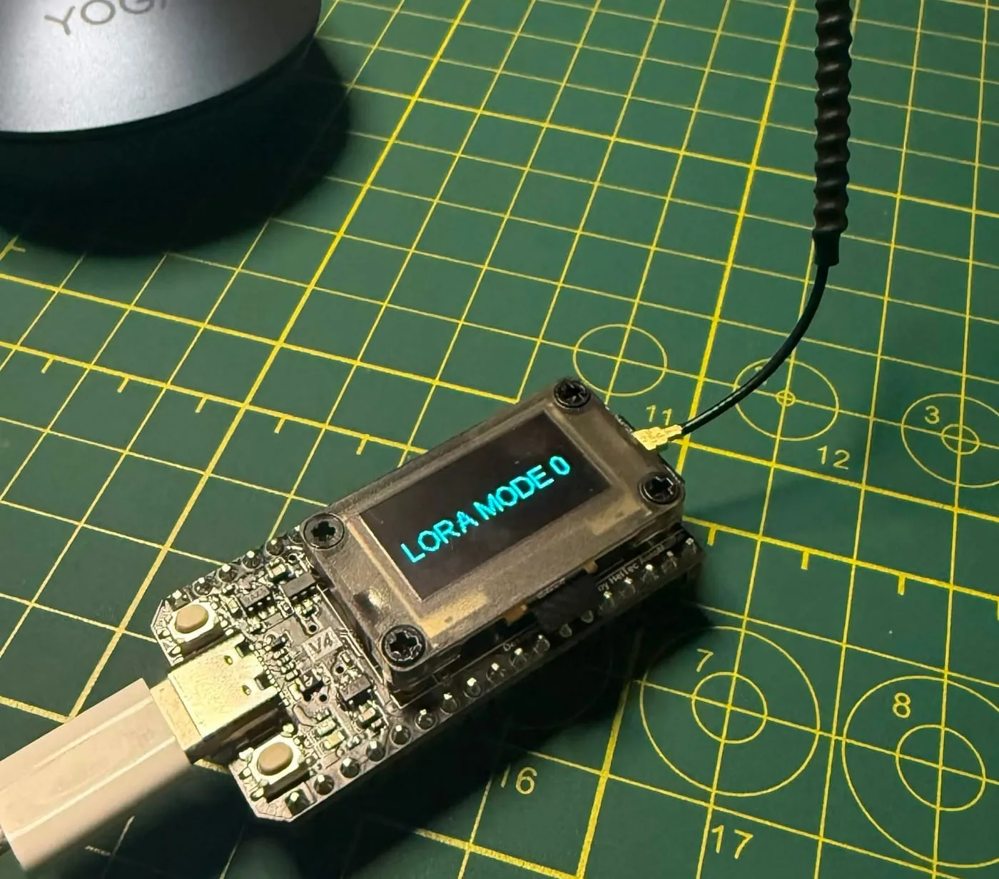 node 1, antenna on before it ever got power. transmitting without an antenna can kill the radio.
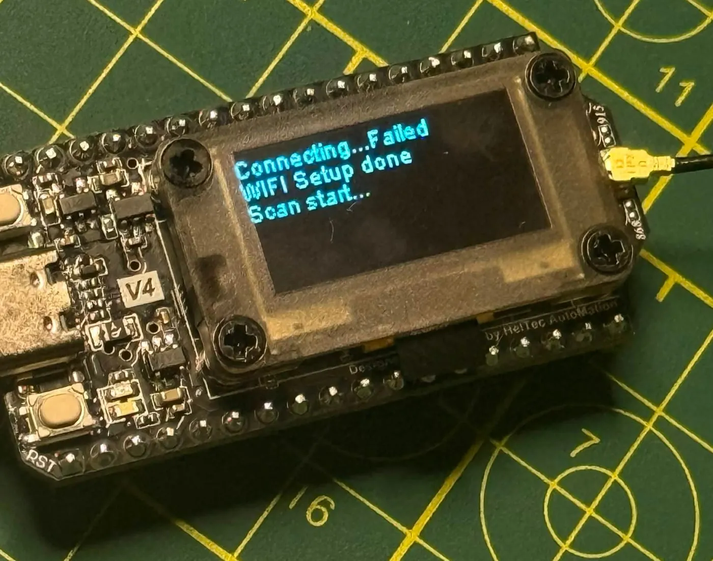 first power up, running whatever it shipped with. not my code yet.
the toolchain is proven, and that’s about it so far. arduino ide 2 with espressif’s esp32 board package, board target set to heltec v3 (the v4 uses the same target), and a blink sketch uploaded, modified to 200 ms, and verified running. esptool reported every written segment as hash verified, and blink used 7% of program storage, so there’s plenty of room. it was my first upload in arduino ide 2. a small milestone, but every piece after this sits on top of it.
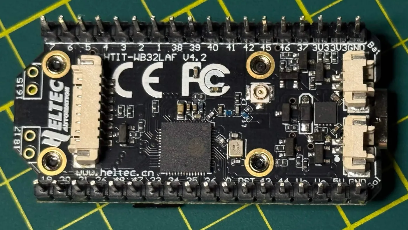 the underside. hw revision htit-wb32laf v4.2.
it’s been paused since blink. the semester comes first.
next
- burn in the mq-2 (and probably the mq-135 alongside it). mq sensors need 24 to 48 hours powered before their readings settle, and garbage readings before then are expected. burn-in only runs the heater, so it’s just 5v and ground with no signal wire, which means the divider doesn’t matter yet.
- dht22 wired and reading to the serial monitor while burn-in runs.
- the mq-2 through the divider, measured first, then a blown out match.
- thresholds on the oled, then wifi and the dashboard, then the lora path.
- nodes 2 and 3 only after node 1 hits every milestone.
thanksgiving break is when i’m hoping to pick it back up.
one honest caveat for later: mq sensors are qualitative. they spike reliably on smoke and gas, but they aren’t calibrated instruments, and nothing here will claim real ppm numbers.